ENECA structural group is not specialized in any particular type of objects. For a developing company, which strives to solidify in the EU design sector for a long time, selection of each further object depends on the market.
What to do to be competitive in such terms?
First, to maximum formalise the design process and automate routine activities. Further, we will examine these processes in detail, but first of all, I will speak about how we have started.
When establishing the Steel Structures Department in 2017, the following programs were selected as the working software:
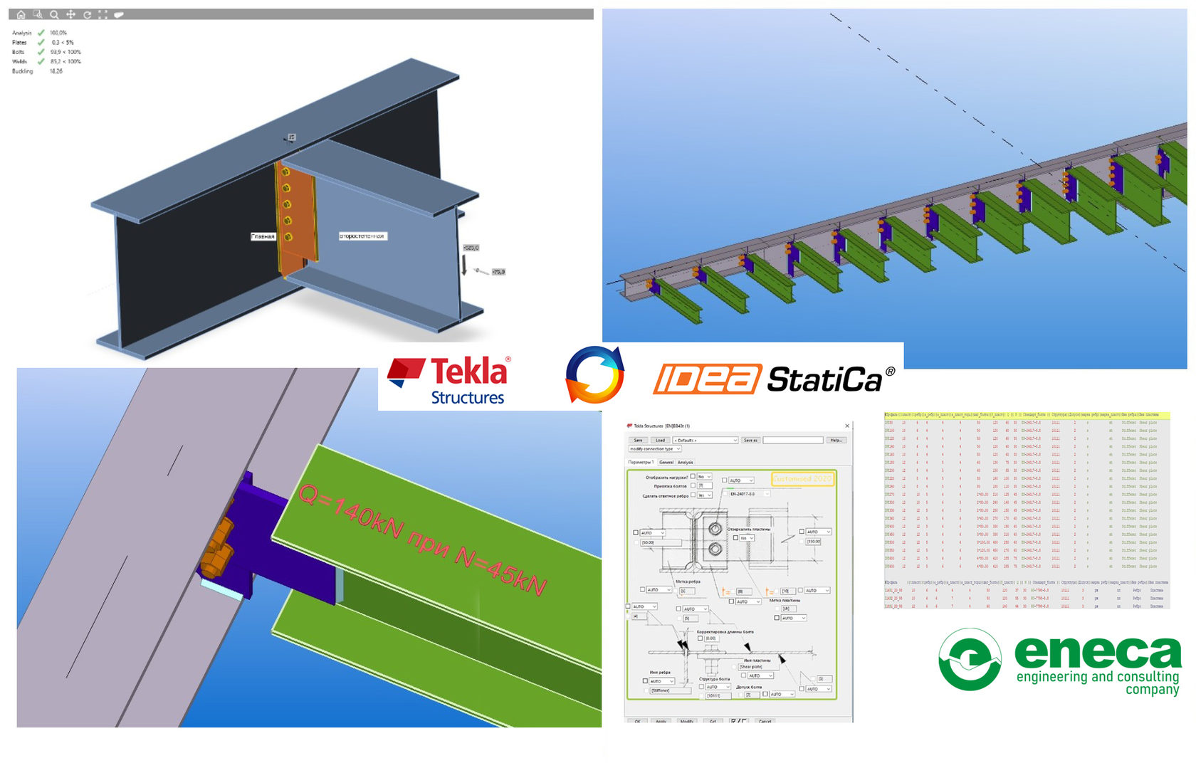
Dlubal RFem – Tekla Structures – IDEA Statica
The main criterion is a mutual connection among the programs.
The programs were selected by the practicing engineers not by the executives, i. e the selected programs were thoroughly tested and work indeed.
Till then, the calculation of structural steel connections had been carried out using the tables made in Excel and Autodesk Robot Structural Analysis, but following this method, the list of the joints is limited by the Excel-tables that are in disposal or hard-coded, which is the case with Robot Structural Analysis. But using only the existing joints and limiting our opportunities at the very beginning is not an advanced and forward looking approach, taking into account that flexibility is one of the main goals for ENECA.
Static calculation – Dlubal RFem;
Calculation of connections – IDEA Statica;
Modelling and issue of drawings – Tekla Structures.
Why IDEA Statica in particular?
When selecting the software for the calculation of connections, IDEA Statica was the best program, which enabled to extract the design combinations from the program for the static analysis. The joint work of Dlubal RFem and IDEA Statica met our requirements to the fullest extent. We consider a quick training for specialists and short-term introduction into the current projects as significant advantages of IDEA Statica. User-friendly interface and intuitive control, visual display of the results, ability to classify the stiffness of the connection for the design scheme of the static analysis, easy preparation of the connection calculation report - all these criteria count in favour of IDEA Statica as it appears from the experience of ENECA engineers.
Due to the fact that connections may be made parametrically in IDEA Statica, it is possible to analyse the most frequently used connections in engineering practice within quite a short period.
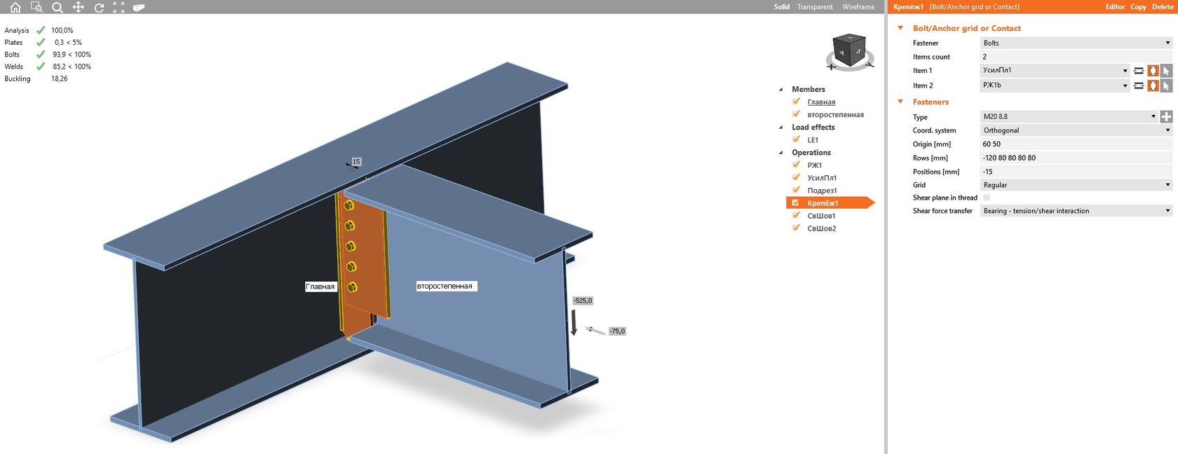
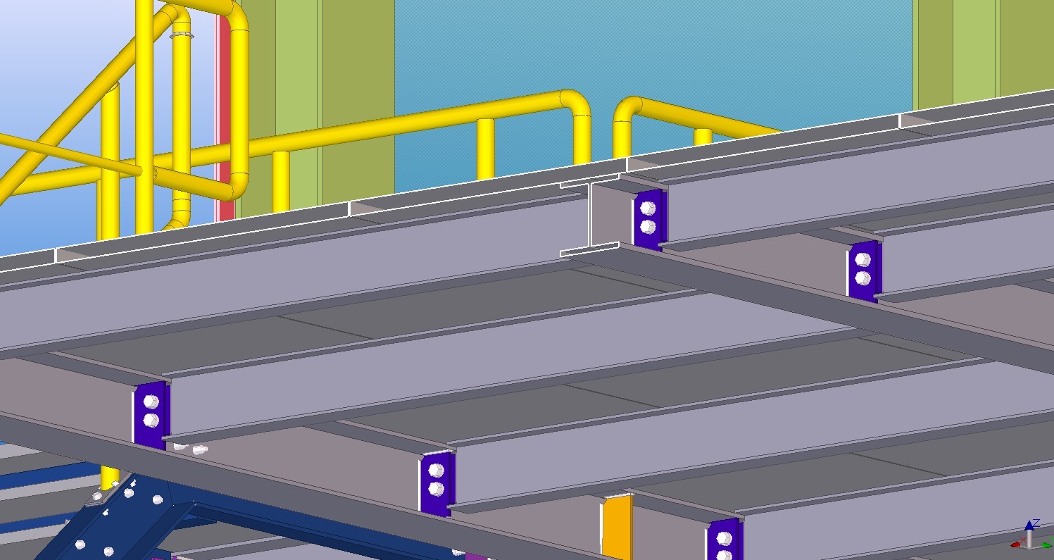
For example, let’s take a look at the simplest connection, component No. 43, which is a standard connection in Tekla Structures.
This component is used almost in all our clients’ facilities as a joint connecting a secondary beam with the main beam in the mezzanines and interfloor slabs.
The flights of the secondary beams are different, the loads all over the surface may be different, as well. An engineer is always up against the selection of the number of bolts and their degree, foot plate and stiffener thicknesses, selection of welds - usual routine work with a huge range of possible solutions and all this is compounded when several specialists work together. It is a common practice in ENECA that simple joints for fastening structural elements are selected by an engineer, who deals with modelling in Tekla Structures. Separate time expenditures for each part of work such as calculation, partial unification, and development of manufacturing drawings for a great number of assemblies resulted in the increase of time needed for the modelling process. Due to all these issues, the procedure needed an urgent automation.
Now, let’s get back directly to formalisation and automation.
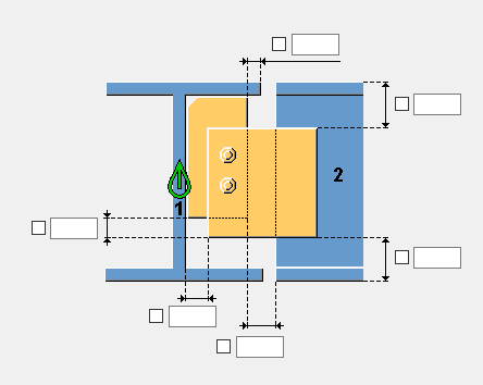
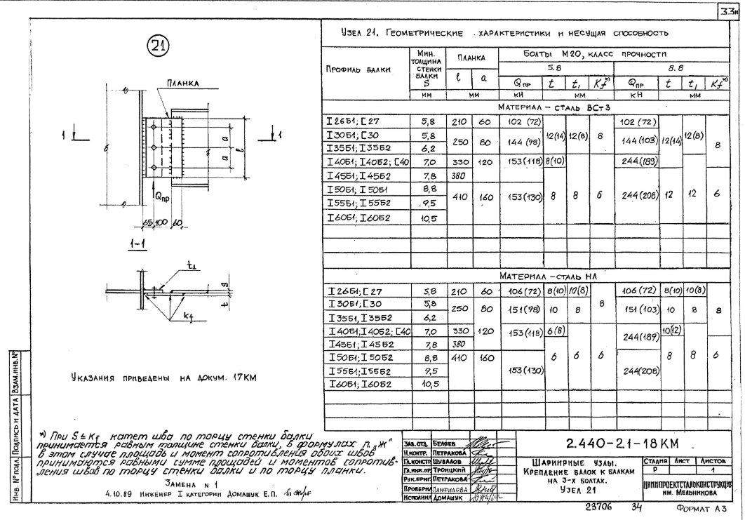
The best example of design process formalisation is the use of typical series of connections for buildings and facilities designed in the post-Soviet countries and well-known for any Soviet engineer. These are such catalogues, where the connection properties may be selected in accordance with the specified criteria and support forces. A good old idea needs only updating.
In 20th century, this work was performed within a long period by a huge state funding design institute including a great number of specialists. How to carry out the work like this now using advanced tools and to the shortest deadline? A piece of cake.
Determine the selection of connection parameters using IDEA Statica, a lot of tools for the process automation may be found in Tekla Structures.
After having determined the acceptable criteria according to plastic deformations, safety factors for bolts and welds, local stability factor for connection parts, let’s get down to the connection analysis.
After analysing the behaviour of the joint together with the rolled beam catalogue, the unification and optimisation of the joint take place - optimal bolt class, weld dimensions and plate thicknesses.
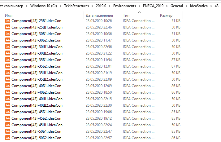
The results of the analysis for each particular joint are summarised into one text file.
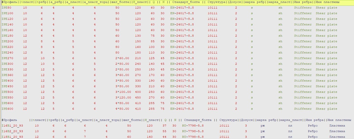
Text file containing analysis results
Then, create a user component in Tekla Structures, the input information of which contains names and properties of the profiles to be connected as well as ultimate values determining support forces of the secondary beam. The connection between the profiles is formed on the basis of the text file generated earlier.
Connection component work window:
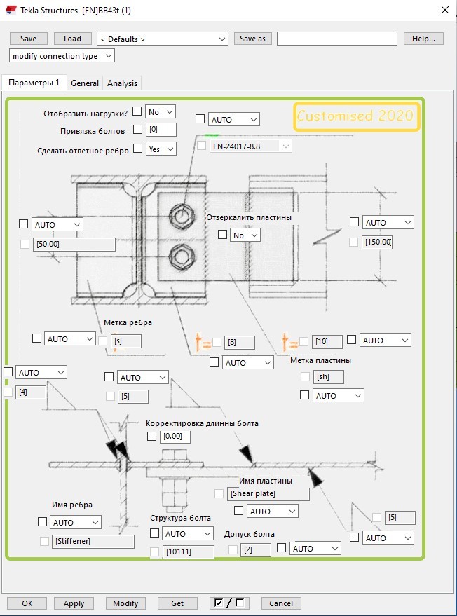
Work window of connection component in Tekla Structures.
It takes 3-4 working days of one specialist to create one simple component. It’s a relatively short time period, but the result brings design to a higher level. Work convenience and speed of use bring joy further down the line.
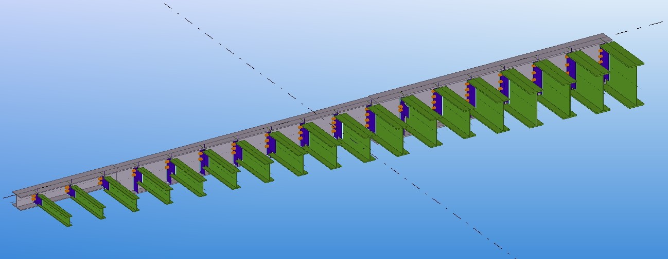
Example of use for a real object:
Such work process optimisation using IDEA Statica covers 90% of possible situations, the accomplished work will help you even in an nontypical case anyway.
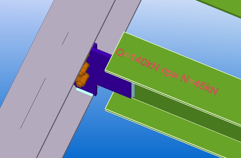
For example, a beam is used as a strut to decrease the design length of the main beam and it experiences only longitudinal forces. Getting back to the initial data of the calculation, then you may change the design combination and verify the connection.
Also, visual information may help - the bearing capacity of the joint calculated using IDEA Statica, which is displayed in the form of a combination of acceptable support forces for the connection. This information is not shown permanently, to display it use a switch, if necessary.
Thus, the automation scheme above enables:
- to accelerate the connection modelling process in Tekla Structures by approximately 40-50%;
- to decrease the involvement of a highly-qualified engineer, who deals with the calculation of the connections in the project, now this specialist deals with the calculation of the nontypical (complex) connections only;
- to involve specialists in modelling connections in Tekla Structures, who have no extensive knowledge and experience in connection calculations; Now the specialist should only know, how to extract the beam forces data from the static calculation model and, in an extreme case, insert these data into the design combination in IDEA Statica and redesign an already calculated connection. Erection procedure as well as bolt and weld connections settings are studied when designing and working on the object.
This information won’t be new for those, who are an old hand at design, but it will be useful for those, who faces a dilemma what software to choose and dip their toe into design.
Thanks for Your attention.